Masonry Wall - Seismic Design
Masonry walls can now be designed for seismic design provisions. Here the process is described.
-
Currently seismic design in masonry walls is only supported under the ACI 530-13 and TMS 402-16/22 codes. All code references given in this topic are specific to these codes.
-
Seismic design will be performed when the following input are met:
-
Supported codes (ACI 530/TMS 402 2013, 2016, or 2022)
-
Seismic design rules are assigned properly
-
Seismic load combinations are used in solution
-
Seismic Design Rules
For seismic design of masonry walls to be performed, the masonry wall panel must be assigned a Seismic Design Rule. Three default Seismic Design Rules are provided in the Seismic Design Rules spreadsheet - Masonry Walls tab as a starting point. Users are responsible to edit/create seismic design rules that fit specific design scenarios.
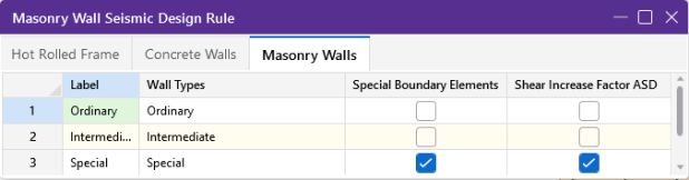
Masonry Wall Seismic Design Rule
|
Column |
Description |
|---|---|
| Label |
The label is a user defined text string that is used as a unique identifier for each of the seismic design rules defined for the structure. The program comes pre-loaded with a number of generic seismic design rules that you can edit to fit their design projects. |
| Wall Type |
These are the three masonry wall types supported for masonry wall seismic design in RISA-3D. |
| Special Boundary Elements |
This setting indicates that the wall will be designed with Special Boundary Elements per Section 9.3.3.6. The program will not check for the maximum area of vertical reinforcement requirements for walls with this checkbox turned on in the seismic design rules. Refer to the Design Considerations section for additional information on checks provided for walls designed with Special Boundary Elements.
|
|
Shear Increase Factor ASD |
This setting applies a factor to the shear demand of the walls with the seismic design rule applied in models solved with TMS 402-22: ASD, TMS 402-16: ASD, or ACI 530-13: ASD codes. The shear increase factor is 2.0 for TMS 402-22: ASD, and 1.5 for TMS 402-16: ASD and ACI 530-13.
|
The following are the three possible states for the Label and Wall Type columns.
-
Ordinary: This wall type will perform design checks based on the minimum reinforcement requirements of Ordinary Reinforced Masonry Shear Walls per section 7.3.2.3.
-
Intermediate: This wall type will perform design checks for Minimum Reinforcement Requirements of Chapter 7, in addition to additional requirements of Intermediate Reinforced Masonry Shear Walls per section 7.3.2.4.
-
Special: This wall type will perform design checks for Minimum Reinforcement Requirements of Chapter 7, in addition to additional requirements of Special Reinforced Masonry Shear Walls per section 7.3.2.5. These requirements include:
-
Additional requirements are checked for Special Reinforced Masonry Walls per section 8.3 (ASD Solution) and 9.3 (Strength Solution) in RISA-3D.
-
Design Considerations
All Wall Panels with Seismic Design Rules applied will be checked for the following Minimum Reinforcement Requirements.
Minimum Reinforcement Requirements
All masonry design walls assigned a seismic design rule will be checked for minimum reinforcement requirements per ACI 530/TMS 402 section 7.3.2. including:
-
Vertical Reinforcement
-
At Wall Ends (for wall regions at the ends of the wall panel)
-
Minimum Bar Size
-
Maximum Bar Spacing Around Openings (for applicable Wall Panel Regions)
-
-
Horizontal Reinforcement
-
At Top of Wall Region
-
Minimum Bar Size
-
Maximum Bar Spacing Around Openings (for applicable Wall Panel Regions)
-
Additionally, all wall types are checked for Mortar type requirements per ACI 530/TMS 402 section 7.4.4.2.2.
Special Reinforced Masonry Walls - Additional Requirements
Additional checks are provided for wall types assigned a “Special” seismic design rule per section 7.3.2.5. These additional checks include:
-
Maximum vertical spacing of vertical reinforcement
-
Shall be the smallest of one-third of the length of the wall region, one-third the height of the wall region and 48 inches.
-
-
Maximum spacing of horizontal reinforcement
-
Shall be the smallest of one-third of the length of the wall region, one-third the height of the wall region and 48 inches.
-
-
Minimum cross-sectional area of vertical & horizontal reinforcement
-
The sum of vertical and horizontal cross-sectional area shall be at least 0.002Ag(vert), where Ag(vert) is the cross-sectional area of the wall panel region (on a horizontal plane)
-
Minimum vertical & horizontal cross-sectional area shall be 0.0007Ag, where Ag is the gross cross-sectional area perpendicular to reinforcement being considered
-
ASD - Additional Requirements
The ACI 530/TMS 402 code has additional seismic detailing requirements for masonry shear wall panels, some of which are considered in RISA-3D. The seismic detailing requirements in this section are only considered if the model is solved using one of the supported Service (ASD) masonry codes.
Max. Flexural Rho Check
Masonry Wall Panels with a Seismic Design Rule of “Special”, a shear span ratio (M/Vdv) ≥ 1, and an axial load ≥ 0.05f’mAn, shall be checked for a maximum reinforcement ratio equal to ρmax, calculated based on TMS 402 Equation 8-18:
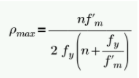
Where:
-
n is the modular ratio of steel reinforcement
-
f’m is the compressive strength of masonry
-
fy is the yield strength of steel reinforcement
ASD Wall Shear Stress Increase Check
Masonry Wall Panels with a Seismic Design Rule of "Special" will be checked if a shear increase factor is applied to the in-plane shear demand as required by section 7.3.2.5.1.1. The program automatically handles this requirement if the "Shear Increase Factor" setting is turned on in the Masonry Walls tab of the Seismic Design Rules spreadsheet, and will apply an increase factor to the shear demand in the wall region. The shear increase factor applied is 1.5 for TMS 402-16 or ACI 530-13: ASD and 2.0 for TMS 402-22: ASD.
![]()
LRFD - Additional Requirements
The ACI 530/TMS 402 code has additional seismic detailing requirements for masonry shear wall panels, some of which are considered in RISA-3D. The seismic detailing requirements in this section are only considered if the model is solved using one of the supported Strength (LRFD) masonry codes.
Special Boundary Elements Requirements
For Masonry Wall Panels with a Seismic Design Rule of “Special” and walls “Special Boundary Elements” setting turned on in the Seismic Design Rule, the program will determine if Special Boundary Elements are required per Section 9.3.5.6.2.1. Two conditions are considered to determine if Special Boundary Elements are required:
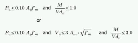
If any of the conditions above hold true, then Special Boundary Elements are not required per Section 9.3.5.6.2.1. If both of the conditions above do NOT hold true, then Special Boundary Elements are required. The program does not design the walls with the Special Boundary Elements. Users shall proceed to the requirements of Section 9.3.5.6.2 for further design requirements if special boundary elements are required.
-
The requirements of Section 9.3.5.6.2.1 are checked per wall panel regions, not the entire wall panel.
-
Wall is assumed to be rectangular in shape and geometrically symmetrical.
-
For wall panels designed using Special Boundary Elements, no checks for maximum vertical reinforcement are required per ACI 530/TMS 402. Refer to TMS 402/602-22 and ACI 530-13 for additional information on ductility requirements.
Design Seismic Shear Capacity Limits
For Masonry Wall Panels with a Seismic Design Rule of “Special”, the program checks if the Design Shear Strength, phi_Vn, exceeds a shear value (Vu) that corresponds to 1.25 times the nominal flexural strength of the wall, calculated as follows:
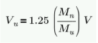
Where:
-
Mn is the in-plane nominal flexural strength of the wall panel region
-
Mu is the in-plane moment (flexure) demand in the wall panel region
-
V is the actual shear demand in the wall panel region
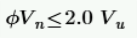
Additionally, per 7.3.2.5.1.2 the Design Shear Strength must not exceed 200% of the shear demand in the wall panel region:
If any of the minimum and maximum limits to the Design Shear Strength is not met, a “Fail” will be indicated in this check in the Seismic Detailing section of the Wall Panel Detail Report for the wall panel region.
Maximum Area of Flexural Tensile Reinforcement (max. Flexural Rho Check - Strength)
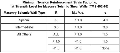
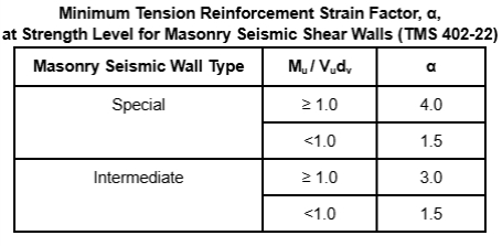
For walls not designed with Special Boundary Elements and designed using a Strength code, wall panel regions will be checked against maximum flexural reinforcement requirements per Section 9.3.3.2 for TMS 402-16 and 9.3.5.6.1 for TMS 402-22. These sections stipulate minimum levels of strain at the extreme tension fiber, which the program handles individually for each wall panel region, with a minimum tension reinforcement strain factor, “α”, for each masonry seismic wall type.
The tension reinforcement strain factor is dependent on the wall type, seismic response modification R factor, and the shear span ratio (M/Vdv) ratio, as shown in the table below:
The strain ratio for the extreme rebar layer, calculated as es/ey, where es is the strain in the steel at the extreme tension rebar layer and ey is the yield strain of reinforcement.
The procedure for determining compliance is as follows:
-
Wall Panel Region in-plane reinforcement design is done based on the flexure (moment) demand in the wall panel region.
-
Shear span ratio (M/Vdv), depth to neutral axis c and seismic response modification R factor are reported.
-
Required minimum tension reinforcement strain factor is obtained per the table above.
-
Strain ratio, calculated as es/ey, where es is the strain in the steel at the extreme tension rebar layer and ey is the yield strain of reinforcement, is compared to α.
-
If es/ey ≥ α, then reinforcement in the wall panel region is in compliance.
-
If es/ey < α, then the reinforcement in the wall panel region is NOT in compliance.
-
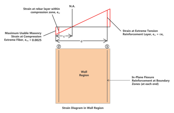
The strain in the steel at the extreme tension rebar layer is calculated based on the depth to neutral axis c, and the effective depth of the wall region, d, as shown in the diagram below:
Click on image to enlarge it
The calculation of the strain at the extreme tension reinforcement layer is as follows:
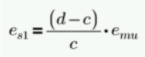

-
Out of plane reinforcement is not considered in meeting ductility requirements for Section 9.3.3.2 (TMS 402-16) and 9.3.5.6.1 (TMS 402-22).
-
The effects of compression reinforcement is considered in the in-plane flexural capacity of the wall panel regions when calculating the location of the neutral axis.
-
The maximum usable masonry strain at the extreme compression fiber, emu, is assumed to be 0.0025 for the calculation of the strain at the extreme tension steel for Seismic Detailing checks. For assumptions of the extreme compression fiber for non-seismic in-plane checks, refer to the In Plane Design - Strength section.
-
Section 9.3.5.6.1 requires axial forces to be taken from the loading combination given by D + 0.75L + 0.525QE. The program has no way of determining if this load combination is present in the model, or if it governs the design of the wall panel. Therefore, it is recommended that users include this load combination in the set of solved load combinations, and determine if ductility requirements are met for this specific load combination.
Assumptions and Limitations
-
All walls are assumed to be laid in a running bond.
-
No checks are provided for seismic detailing requirements at roof and floor diaphragms, at wall corners, for dowels or through control joints. Additional requirements may apply for seismic design categories D, E and F. Refer to TMS 402-16 or ACI 530-13 Chapter 7 for additional requirements.